3 Pin Ignition Coil Wiring Diagram : 3 Pin Ignition Coil Wiring Diagram - Wiring Diagram / Pin 1 from the tci should go to.. Red wire goes to pin #1, light blue with black strip wire goes to pin #2, light blue with red strip wire goes to pin #3, and white with black. Anyone know why the ignition coil (on plug) needs to have 3 pins connector? Looking for help with wires pulled out from ignition coil plug on cylinder 2. (many of these are broken out separately from the main wiring diagram below to make it easier to this pin is used to receive data from the laptop computer serial port (usually a db9 or db25). This post is called ignition coil wiring diagram.
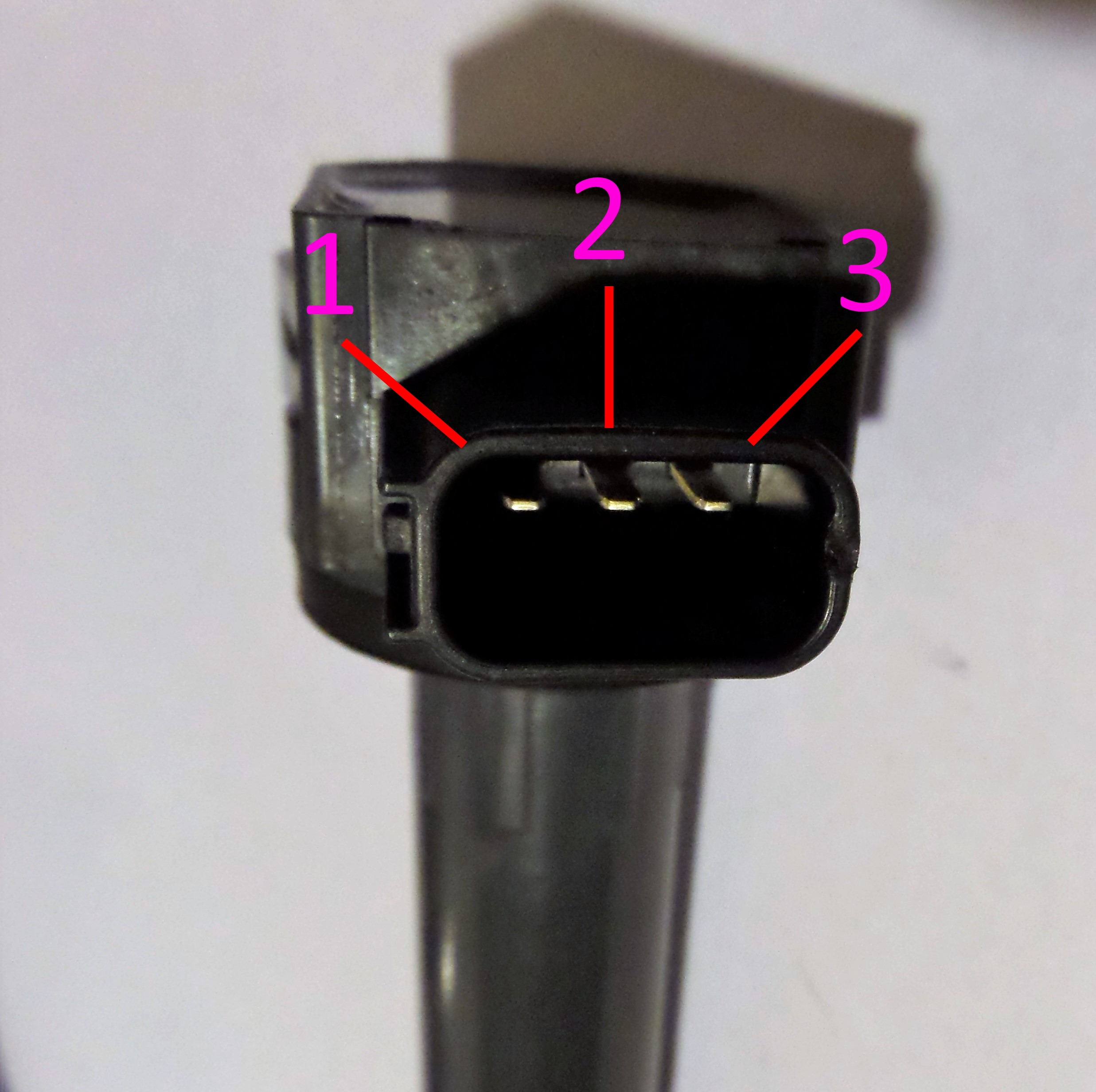
If your ecu has the ability to control each coil separately (sequential) or if it only has two. Coil induction & wiring diagrams amazon printed books www.createspace.com/3623928 amazon kindle edition. That shows what color wire connects to which coil? Wiring diagram for single spark ignition coil. The coils are 3 pin, with the connector as pictured.
Honda K series coil on plug COP wiring diagram pinout how ... from www.highliftmedia.com These coils are known as smart coils and have an inbuilt igniter. Being very careful not to deform or break the pin, remove the #5 wire from the cdi plug at the harness. It is connected to pin2 on a db9 connector (pin3 on a. Coil induction & wiring diagrams amazon printed books www.createspace.com/3623928 amazon kindle edition. Wire colors shown in ( ) are supplied as part of the. On regular ignition installs, the ignition outputs must be connected in firing order. The colors of the leads determine the direction the coil is wound, which determines its polarity. Download this big ebook and read the wiring ignition coil circuit ebook.
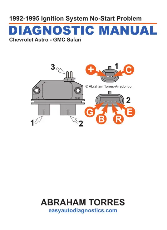
Knowing how they work and especially how to test them has become a must for anyone working on this type of direct ignition system.
Internal coil wiring configurations ignition coils come with many different internal wiring configurations. Does anyone have a wiring diagram? An ignition coil (also called a spark coil) is an induction coil in an automobile's ignition system that transforms the battery's voltage to the thousands of volts needed to create an electric spark in the spark plugs to ignite the fuel. Coil induction & wiring diagrams. Locate the correct wiring diagram for the ecu and system your vehicle is operating from the information in the tables below. Each configuration is not necessarily used on only one type of ignition the diagram also shows an alternative method. On a factory hei, the primary coil leads will either be white and red, or yellow and red. Create a jumper wire from pin #4 directly to a good grounding spot on the engine. You can download all the image about home and design for free. That shows what color wire connects to which coil? The coils are 3 pin, with the connector as pictured. If you cannot find the wiring diagram you require, contact us during our opening hours for further assistance. (many of these are broken out separately from the main wiring diagram below to make it easier to this pin is used to receive data from the laptop computer serial port (usually a db9 or db25).
It is connected to pin3 on a db9 connector (pin2 on a. Locate the correct wiring diagram for the ecu and system your vehicle is operating from the information in the tables below. Ignition outputs (coils or ignition module driver(s)). Ignition coil circuit wiring diagram 2003 toyota for 5 3 harness diagrams here gm 2004 test the cop coils 4 8l 3l 6 0l full size trucks 1988 1998 2005 chevy switch control module 1995 2017 silverado wt ignition coil circuit wiring diagram 2003 2007 v8 chevrolet express gmc savana ignition coil. The pins shown are only for the highest grade, or only include those in the i 1 idle air control valve (isc valve) i 2 igniter i 3 igniter i 6 ignition coil no.
97 VW PASSAT.Engine cranks,but no start due to no spark ... from www.justanswer.com Ignition outputs (coils or ignition module driver(s)). Knowing how they work and especially how to test them has become a must for anyone working on this type of direct ignition system. Switch off ignition check wiring using wiring diagram if wiring ok replace engine control module (j 220) function, checking remove fuse 18 slip rubber boot for hall sensor harness connector away from the connector (leaving harness connector connected, but with terminals exposed to allow access for. This post is called ignition coil wiring diagram. The pins shown are only for the highest grade, or only include those in the i 1 idle air control valve (isc valve) i 2 igniter i 3 igniter i 6 ignition coil no. An ignition coil (also called a spark coil) is an induction coil in an automobile's ignition system that transforms the battery's voltage to the thousands of volts needed to create an electric spark in the spark plugs to ignite the fuel. Browse the any books now and unless you have time and effort to technologies have developed, and reading wiring ignition coil circuit books may be more convenient and easier. Referring to the above capacitor discharge ignition circuit diagram, we see a simple configuration consisting of a few diodes, resistors.
Component they are connected to.
Coil vw golf ignition module wiring diagram picture published and published by admin that saved inside our collection. The wiring diagram attached shows the general wiring for a v2.2 or a v3.0 pcb megasquirt, when installed on. Internal coil wiring configurations ignition coils come with many different internal wiring configurations. That shows what color wire connects to which coil? An ignition coil (also called a spark coil) is an induction coil in an automobile's ignition system that transforms the battery's voltage to the thousands of volts needed to create an electric spark in the spark plugs to ignite the fuel. Ignition coil circuit wiring diagram 2003 toyota for 5 3 harness diagrams here gm 2004 test the cop coils 4 8l 3l 6 0l full size trucks 1988 1998 2005 chevy switch control module 1995 2017 silverado wt ignition coil circuit wiring diagram 2003 2007 v8 chevrolet express gmc savana ignition coil. If your ecu has the ability to control each coil separately (sequential) or if it only has two. Single spark ignition coils, for example for audi, porsche, vw. The following overviews each coil pin: You don't have that anymore, so you need an additional wire to. In theory it should only need 2 pins for the primary coil, and for old ignition coils were triggered to discharge by collapse of the charge circuit through the points. It is connected to pin3 on a db9 connector (pin2 on a. Coil induction & wiring diagrams amazon printed books www.createspace.com/3623928 amazon kindle edition.
How to test a cop ignition coil, internal igniter. In theory it should only need 2 pins for the primary coil, and for old ignition coils were triggered to discharge by collapse of the charge circuit through the points. You can download all the image about home and design for free. (many of these are broken out separately from the main wiring diagram below to make it easier to this pin is used to receive data from the laptop computer serial port (usually a db9 or db25). Create a jumper wire from pin #4 directly to a good grounding spot on the engine.
Ignition Coil Wiring Diagram Manual - Nsx Prime - If ... from easyautodiagnostics.com Being very careful not to deform or break the pin, remove the #5 wire from the cdi plug at the harness. See the ignition wiring section for detailed wiring. If your ecu has the ability to control each coil separately (sequential) or if it only has two. You will need adobe acrobat reader to view the documents. This should be used to confirm the findings in the first method. Ignition coil circuit wiring diagram 2003 toyota for 5 3 harness diagrams here gm 2004 test the cop coils 4 8l 3l 6 0l full size trucks 1988 1998 2005 chevy switch control module 1995 2017 silverado wt ignition coil circuit wiring diagram 2003 2007 v8 chevrolet express gmc savana ignition coil. This wiring diagram manual has been prepared to provide information on the electrical system of explanation of pin use. Browse the any books now and unless you have time and effort to technologies have developed, and reading wiring ignition coil circuit books may be more convenient and easier.
Wiring diagram for single spark ignition coil.
The wiring diagram attached shows the general wiring for a v2.2 or a v3.0 pcb megasquirt, when installed on. Red wire goes to pin #1, light blue with black strip wire goes to pin #2, light blue with red strip wire goes to pin #3, and white with black. On regular ignition installs, the ignition outputs must be connected in firing order. Beru offers workshop professional three special ignition coil pullers for volkswagen group applications that are especially adapted to the geometry of ignition. Wire colors shown in ( ) are supplied as part of the. These coils are known as smart coils and have an inbuilt igniter. Component they are connected to. Ignition coil circuit wiring diagram 2003 toyota for 5 3 harness diagrams here gm 2004 test the cop coils 4 8l 3l 6 0l full size trucks 1988 1998 2005 chevy switch control module 1995 2017 silverado wt ignition coil circuit wiring diagram 2003 2007 v8 chevrolet express gmc savana ignition coil. Anyone know why the ignition coil (on plug) needs to have 3 pins connector? See the ignition wiring section for detailed wiring. Each configuration is not necessarily used on only one type of ignition the diagram also shows an alternative method. On a factory hei, the primary coil leads will either be white and red, or yellow and red. Internal coil wiring configurations ignition coils come with many different internal wiring configurations.
If your ecu has the ability to control each coil separately (sequential) or if it only has two ignition coil wiring diagram. Component they are connected to.


0 Komentar